

Vacuventve series
ve series
The Dual Function air valve
Vacuvent offers a dual-function air valve that not only breaks vacuum but also
releases air under operating conditions.
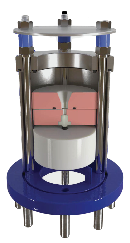
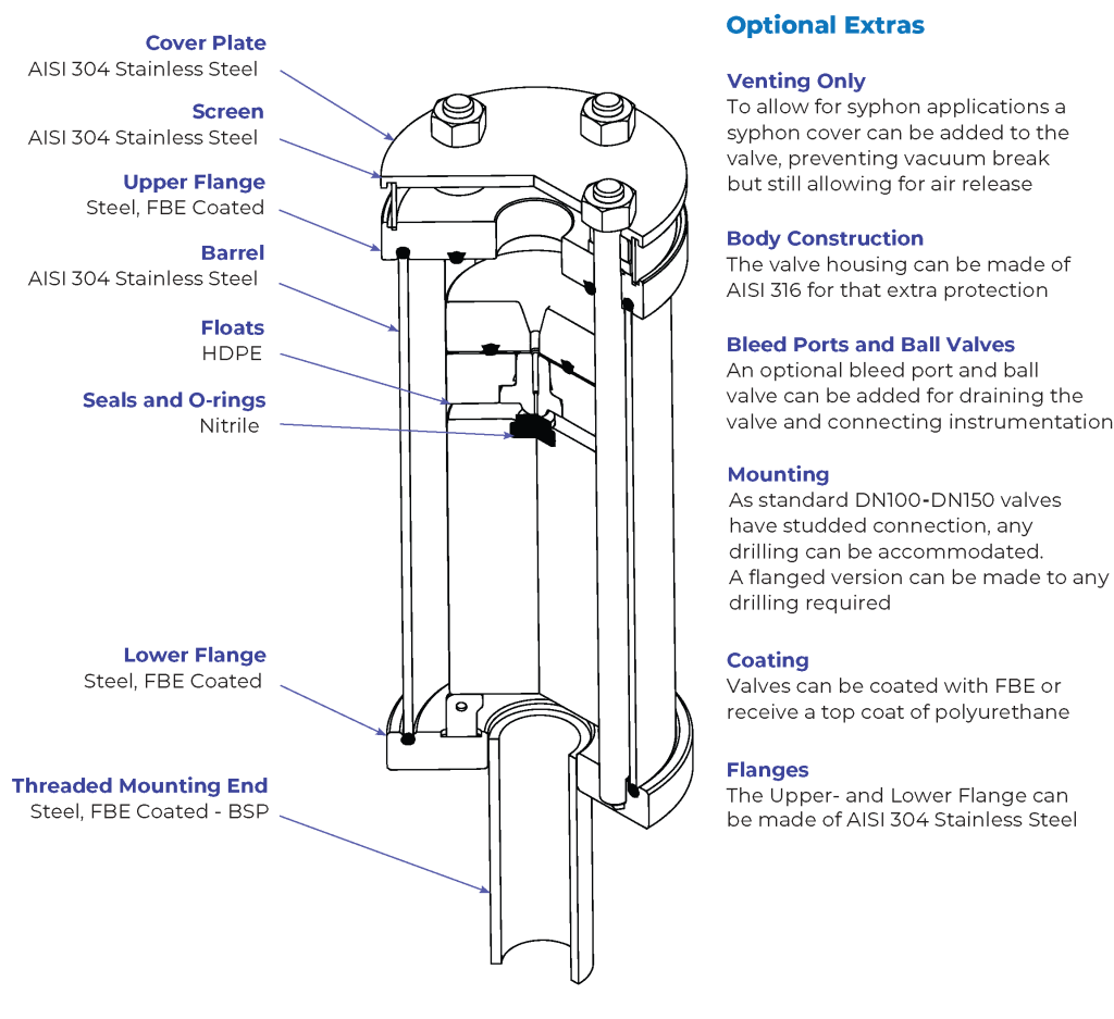
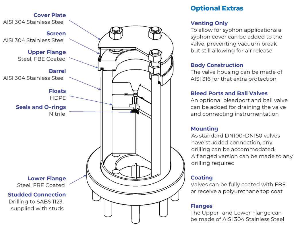
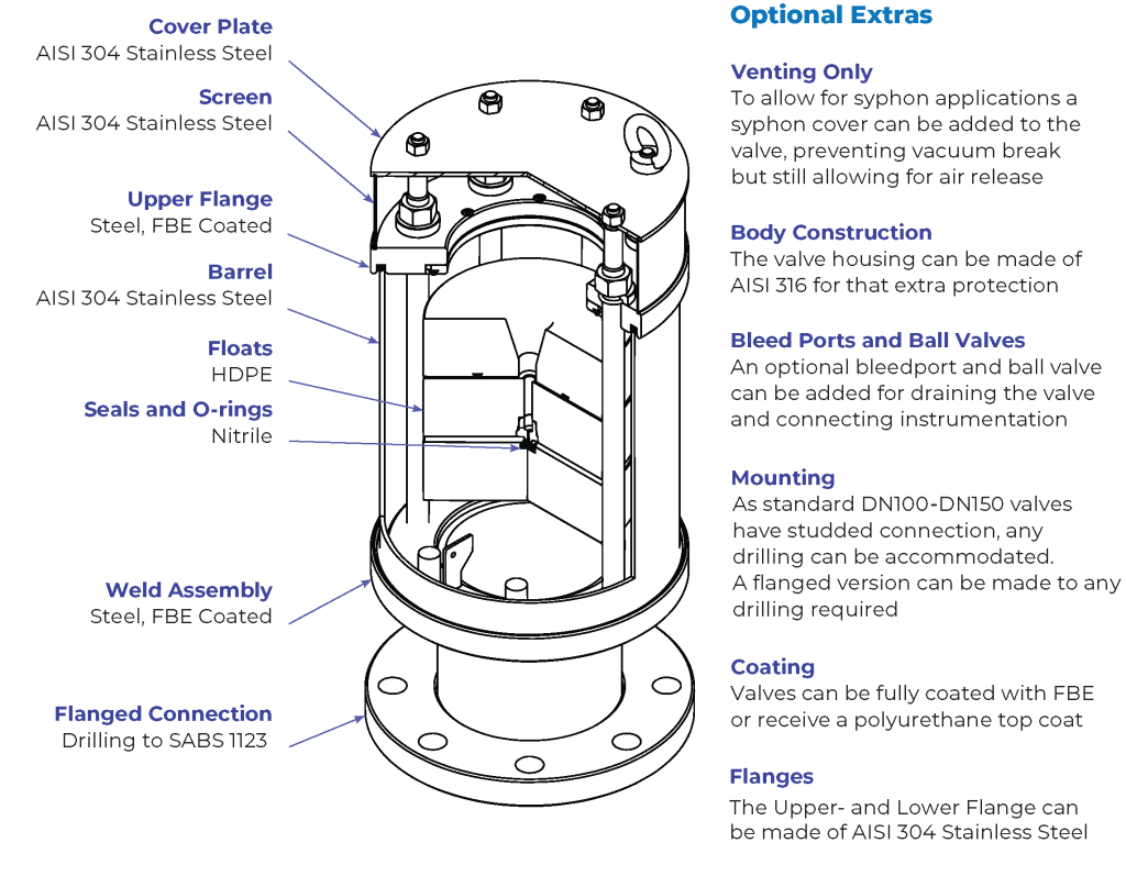
Materials
The body is made out of stainless steel and the flanges are mild steel, FBE coated. The floats are made of HDPE and the nozzle is made of Ertalyte TX, a semi-crystalline thermoplastic polyester that operates well under both high pressure and velocity conditions.
Due diligence plan
With solid HDPE floats, rest assured that the internal mechanisms will not deform under pressure. The cylindrical design also increases the effectiveness of the valve’s operation during vacuum conditions. The fabricated tubular body construction allows for cost effective use of corrosion resistant materials.
Design Considerations
Sizing
All Vacuvent valves are full have an intake area equal to the full bore of the valve. This means that the flow area at any given point is equal or greater than the specified nominal bore area. Most sizing is based on the need to protect the pipeline from a negative pressure, vent the initial air, and to vent the pressurized air with the importance generally in that order. A good start is to select a scouring or drainage rate based on rupture or draining of 2-3 times the designed flow rate of that particular section. Size the AV to protect the pipeline and seals from low pressure within the pipeline during draining or other pipeline disturbances (eg. pump trip). One accepted method is to limit the internal pressure to 3.5m P (0.35Bar) below atmospheric @ sea level. The AV performance data in “Software Design Parameters page” indicates that point and the resultant inflow of air. For a more dynamic estimation see the Toolbox fly out on the website which allows the user to check individual sections to size the AV dynamically and run some “what if” scenarios.
POSITIONING
Vacuum break valves should be located on every apex of a pipeline, should any pipe rupture, or scour be opened, the valve should allow air to enter the line from the highest point. The graphic shows most of the common places where AV (air release valves) are fitted. High points are a natural start, also where the pipeline crosses obstacles like rivers and roads. Check for syphon application above the hydraulic grade line. To control pump start and pump trip, AV should be placed before and after the check valve.
Design Parameters
We have manufactured and designed air release valves for years. The Vacuvent design allowed us to look at various factors from manufacture, service, materials to performance. The process has been driven largely by the now prevalent use of hydraulic predictive programs. The subsequent software data together with actual testing has led us to a more optimized valve.
Intake with Coefficient of Discharge Applied
(normal m3/h)
Valve Size (DN – mm)
Pressure (Bar) | 25 | 50 | 80 | 100 | 150 | 200 |
|---|---|---|---|---|---|---|
-0.05 | 64.4 | 257.7 | 659.7 | 1030.7 | 2319.2 | 4123.0 |
-0.1 | 87.3 | 349.0 | 893.5 | 1396.1 | 3141.2 | 5584.4 |
-0.2 | 115.0 | 460.0 | 1177.7 | 1840.1 | 4140.2 | 7360.4 |
-0.3 | 130.7 | 523.0 | 1338.8 | 2091.8 | 4706.6 | 8367.2 |
-0.35 | 135.6 | 542.2 | 1388.0 | 2168.8 | 4879.9 | 8675.3 |
-0.4 | 138.7 | 554.6 | 1419.8 | 2218.5 | 4991.5 | 8873.8 |
-0.5 | 140.4 | 561.4 | 1437.2 | 2245.7 | 5052.8 | 8982.7 |
The coefficient of discharge on intake is Cd=0.4
The recommended design intake should not exceed 0.35Bar
After a differential pressure of 0.5Bar the valve will be in the choke condition and where lower pressures will not increase intake capacity
Venting with Coefficient of Discharge Applied
(normal m3/h)
Valve Size (DN – mm)
25 | 50 | 80 | 100 | 150 | 200 | |
|---|---|---|---|---|---|---|
At PN | 16 | 30 | 43 | 43 | 84 | 121 |
The coefficient of discharge on venting is Cd=0.8
The above values are at the valve design pressure
Sizes
Valve Size (DN – mm)
25 | 50 | 80 | 100 | 150 | 200 | |
|---|---|---|---|---|---|---|
PN Bar | 25 40 | 25 40 | 25 40 | 25 40 | 25 40 | 25 40 |
Anti-Shock mm | 3.3 4.2 | 6.5 8.5 | 10.5 13.5 | 13.5 17 | 20 25.5 | 27 34 |
Small Orifice mm | 1.2 0.9 | 1.5 1.2 | 1.8 1.4 | 1.8 1.4 | 3 2 | 3 2.4 |
Through Area mm2 | 491 | 1963 | 5027 | 7853 | 17671 | 31416 |
Modes
Operation
The valve has two operating modes, vacuum break
and air release under operating conditions. The valve operates automatically, with the different modes being
triggered by the float system contained inside.

Pressurized Air Release
During operation any pipeline will have air accumulating in the pipeline, this can cause lower volumetric flow rates and strain on the pipes & pumps. It is for this reason that air needs to be released, which is where the bleed nozzle comes in play on this Vacuvent Air valve, releasing air at operating pressure.

Vacuum Break
When a pump trips, or the pipeline is being scoured, a vacuum develops inside the line, this can lead to catastrophic failure pipeline. The Vacuvent VE series valve breaks the vacuum and opens to allow air into the pipeline to break the vacuum pressure to the full bore of the air valve itself.
Standard Body Construction
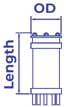
Dimensions
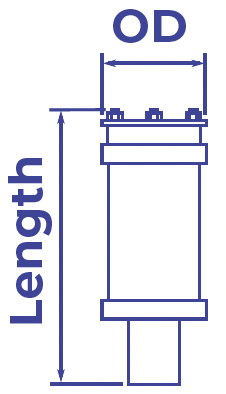
DN mm | PN kPa | OD mm | Length mm | Weight kg | Bleed | OD mm | Anti-Shock OD mm |
|---|---|---|---|---|---|---|
25 | 25 | 100 | 328 | 5 | 1.1 | 3.3 |
40 | 100 | 350 | 6 | 0.9 | 4.2 | |
50 | 25 | 120 | 365 | 7 | 1.5 | 6.5 |
40 | 120 | 380 | 8 | 1.2 | 8.5 |
Dimensions
DN mm | PN kPa | OD mm | Length mm | Weight kg | Bleed | OD mm | Anti-Shock OD mm |
|---|---|---|---|---|---|---|
80 | 25 | 200 | 344 | 16 | 1.8 | 10.5 |
40 | 153 | 360 | 18 | 1.4 | 13.5 | |
100 | 25 | 180 | 383 | 20 | 1.8 | 13.5 |
40 | 180 | 400 | 24 | 1.4 | 17 |
Dimensions
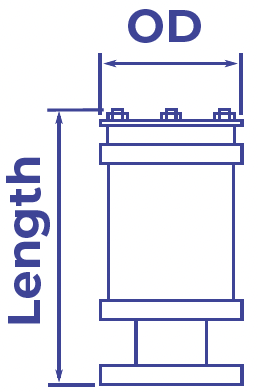
DN mm | PN kPa | OD mm | Length mm | Weight kg | Bleed | OD mm | Anti-Shock OD mm |
|---|---|---|---|---|---|---|
150 | 25 | 290 | 620 | 60 | 3 | 20 |
40 | 290 | 648 | 68 | 2 | 25.5 | |
200 | 25 | 338 | 700 | 90 | 3 | 27 |
40 | 338 | 748 | 104 | 2.4 | 34 |
Dimensions and weights dependent on chosen options
Operating Temperature: 4°C to 85°C
Low head sealing pressure: 0.5Bar
Hydro-static Test Pressure: 2xPN